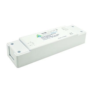
DALI AC Dual Constant Current LED Driver
PRODUCTS
Specification
Technical Data
| Model | AGD-LA132CA2 | |
|---|---|---|
| Input | Voltage/Hz | 100...240V AC, 50...60Hz |
| Leakage | < 0.25mA | |
| Standby W | < 0.5W | |
| Power Factor | > 0.95 ? | |
| Harmonic | 15% ? | |
| Output | Voltage | Max 55V, Nominal 3...45V, dual CC circuit |
| Current | Nominal 0.1...1A, default 300mA, programmable | |
| Power | Max 36W in total of both channels | |
| PSTLM | <= 1 | |
| SVM | <= 0.4 | |
| Protection | Surge capability | L/N-Ground 2kV, L-N 1kV |
| Short | Programmable protection point | |
| Open | Programmable protection point | |
| Load Change | Realtime measure voltage and current | |
| Isolation | Main input/output SELV, output/DALI FELV, main input/DALI FELV | |
| Environment | Temperature | Ta: -30...+50℃, Tc: 70℃ |
| Humidity | 20...95% | |
| Storage | -40...+80℃, 10...95% | |
| Dimming | DALI | DALI-2 IEC 62386 101, 102, 207, 209, 251, 252, 253 |
| Dim Mode | Dual CC, Dual output, no common pin, mixed dimming | |
| Others | Det. & Data | Input/Output power, accumulated power, on time, PF, etc. |
| Dimension | 192*54*35mm | |
| Weight | 220g | |
Installation
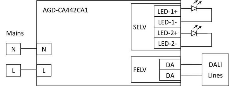
Wiring and circuit diagram
- For better EMC, keep wires between drivers and LEDs as short as possible.
- No invers-polarity protection of LEDs is supported.
- No common pole is supported. Two LED strips should be connected separately.
- Wrong wiring of LED drivers may damage the driver, LEDs, and DALI bus.
- The wiring must be short-circuit protected from earth wire, to avoid dysfunction and damage.
- DA/DA terminals are for DALI bus wires, and they are cataloged FELV, and should be connected to FELV circuit.
Wiring cable and cross section
The cable cross-section of each terminal can be 0.75...1.5mm2, and the wire preparation length can be10.0…11.0mm. Each terminal should be used one wire only.
Hot plug-in
Hot plug-in is not recommended due to the driver’s residual output voltage. Hot plug-in will cause high inrush current and damage the LEDs. Power-off and 15 seconds of cold down is recommended for the installation.
Usage and install
The LED driver is intended to be used as a built-in driver (marked ◎), it must be installed within a luminaire enclosure or protected from human and environment (usually in house ceilings). Good ventilation and 10…15 cm distance from heat source is recommended.
LED current adjust
The LED driver’s output current can be programmable with SmartLink tool. The minimum output current is varied over LED voltage. Please, check its operating window for its limitation.
Electrical values
- Operating window
- Efficiency vs load
- Power factor vs load
- THD vs load
- Harmonic distortion
Functions
Short-circuit protection
A short circuit at LED output will trigger the driver’s safeguard and turn off its output. It can be restarted by reset its mains or dim off-and-on with DALI tools.
Open-circuit/no-load protection
An Open circuit at LED output will also trigger its safeguard and turn off its output. It can be restarted by reset its mains or dim off-and-on with DALI tools. Its output will constantly lower to about zero voltage. No-load or open-circuit will not cause harm to the driver, however, a hot-plug or change of LED engine or luminaires are not recommended. Residual voltage will cause permanent damage to LEDs.
Over-temperature protection
The driver is equipped with temperature sensor, and it will protect against over-temperatures by lowering its output or shutdown when over its curie point. When it is shutdown, you can restart only when its temperature is lower than its safeguard level (usually is Tc – 30). The temperature sensing points are usually located on the hottest points and micro-controller.
Power metering
The driver will monitor and accumulate its input and output power and save to its EEPROM. The driver is designed to accumulate and save the data at 60 second period for 10 years. A power interrupt may cause missing of some accumulated data.
Health diagnostic
The driver’s electronic output and input data are measured and readable via DALI data protocol. These data are monitored at run-time and valid after 60 seconds of power-up.
Tunable white dimming
This driver uses two constant current drivers to drive two different LED strips, and it manipulate the color temperature by driving different current to different LED strips. The advantage of this technique is to cease the color flickering, but, it may not retain the curve of color temperature at low output level.
Software
This driver is supported by SmartLink configuration tool. You can use SmartLink tool to download and program its parameters such as output current, thermal protecting point, dimming frequency and or many others.
Others
- Risk of electrical shock and energy hazard. All failure should be examined by a qualified technician. Please do not remove the case of the power supply by yourself!
- The openings should be protected from foreign objects or dripping liquids.
- Please do not install LED power supplies in places with high ambient temperature or close to fire source. Please refer to the specifications about the maximum ambient temperature limitations.
- Output current and output wattage must not exceed the rated values on the specifications.
- If the external flexible cable or cord of this switching power supply is damaged, it shall be exclusively replaced by the manufacturer or his service agent or a similar qualified person in order to avoid a hazard.
- LED power supply needs to be disposed together with lighting equipment after the end of its life.
- The DALI is designed as FELV circuit, its terminal shall connect to FELV circuit. Connecting to SELV will lower its isolation level to FELV.


